
The New Network Infrastructure
The CNR Research Area in Firenze consists of five main buildings housing research institutes with offices, laboratories, and data-centres. Each building in the area has a rectangular floor plan and is developed over 2 or 3 floors; on each floor, there are 4 cabinets (one in each corner) that house the network switches connecting the
adjacent laboratories and offices via copper Ethernet cables.
The current internal network infrastructure within the Research Area supports a maximum data transmission speed of 1 Gbps; the existing fibre optic cables do not support higher transmission speeds. For this reason, an upgrade of the current infrastructure was necessary to enable communication adequate to the volume of data used within the EMM computing infrastructure.
The network has been upgraded to incorporate state-of-the-art data transmission technologies, ensuring high-speed connectivity between the data-centres and various network nodes across multiple buildings. The architecture, components, and installation details presented herein provide a comprehensive overview of the new network infrastructure. An more accurate description can be found in the technical document available at CNR-IFAC institute.
General Architecture
The new network was implemented with the purpose of connecting the EMM computing infrastructure, installed within the CNR Research Area in Florence, to a high-speed network using the latest data transmission technologies.
The new network has a star topology; it allows 100 Gbps connections between the data-centres of the INO, IBE, and IFAC institutes, and a 10 Gbps connections to all other devices.
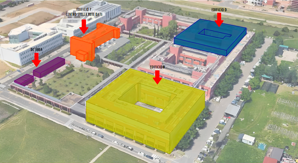
The buildings involved in the network upgrade are those that host components of the EMM
computing infrastructure (see Figure 1); In details:
- Building “B”, which houses the EMM data-centres and the computers used for model development and data analysis by CNR-INO and CNR-IFAC institutes;
- Building “D”, which houses the computers used for model development and data analysis by CNR-IBE institute are located;
- Building “DC-Area”, which houses the data-centres of CNR-IBE institute;
- Building “F”, which houses the network core and the external link to the Internet
External Backbone
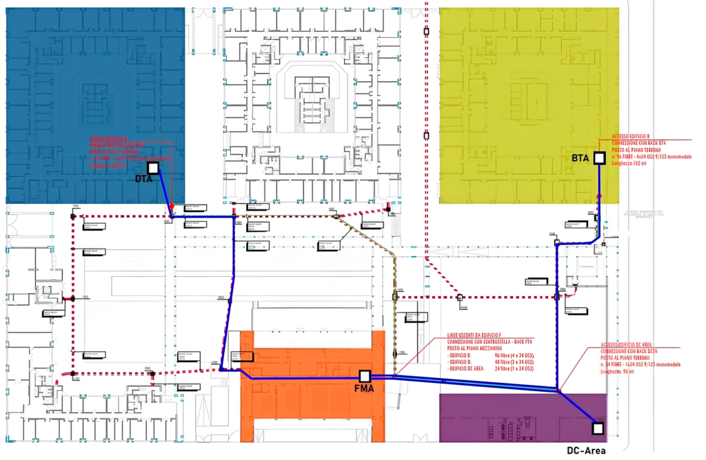
The new external backbone consists of a connection between Building “F” (network core) and Buildings “B”, “D”, and “DC-Area” (see Figure 2). The cables are routed through existing underground conduits, following the paths indicated by the blue lines in Figure 2).
The optical cable used consists of 24 OS2 fibres, 9/125μm, built with a loose-tube single-sheath structure, filled with moisture-resistant gel, and protected with a corrugated steel anti-rodent layer, suitable for outdoor installation.
- Between Building “F” and Building “B”: 4 cables with 24 fibres each, for a total of 96 OS2 optical fibres;
- Between Building “F” and Building “D”: 2 cables with 24 fibres each, for a total of 48 OS2 optical fibres;
- Between Building “F” and Building “DC-Area”: 1 cable with 24 fibres, for a total of 24 OS2 optical fibres;
In Building “F”, all fibres are terminated and connected in an optical distribution frame housed in the core rack; in Buildings “B,” “D,” and “DC-Area,” the fibres are terminated in a rack, located at ground-floor, that serves as a distribution point and connected in an optical patch-panel. From each of the three distribution points start the new fibres that are routed inside the building to reach each network node within the respective building.
Fibre Optic Line - Internal
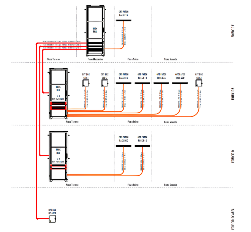
In each of the three buildings, from the rack acting as the distribution point where the external fibres terminate, internal fibres branch off and are routed through the building to reach each network node (see Figure 3). The internal infrastructure is physically separated from the external backbone; internal fibres connect to the external backbone within the optical patch panel installed in the distribution rack. This architecture was chosen as it provides flexibility for activating new nodes or modifying the configuration of existing ones.
The network nodes are:
- For Building “B”:
– 2 network nodes on the ground floor, in the INO and IFAC data-centre;
– 2 network nodes on the first floor, hosting the switches connected to the devices in adjacent rooms;
– 3 network nodes on the second floor, hosting the switches connected to the devices in adjacent rooms; - For Building “D”:
– 2 network nodes on the first floor, hosting the switches connected to the devices in adjacent rooms; - For Building “DC-Area”:
– 1 network node in the IBE data-centre; - For Building “F”:
– 1 network node on the first floor, hosting the switches connected to the devices in adjacent rooms;
For each network node, 4 pairs of fibres are provided; the fibres are connected and terminated in
an optical patch panel.
Active Equipment – Network Switches
Alongside the passive infrastructure, consisting of optical fibres, patch panels, fibre jumpers, etc., network switches were provided for the core (central hub) and for several network nodes located in the various buildings. All devices were installed, configured, and tested.
For the network core we selected switches with 48 fibre ports at 10 Gbps and 6 fibre ports at 100 Gbps, redundant power supply and option for expansion with stackable mounting solutions. For the network nodes in the individual buildings, switches with 4 fibre ports at 10 Gbps and 24 copper ports at 1 Gbps were selected
Note on the Connection Architecture
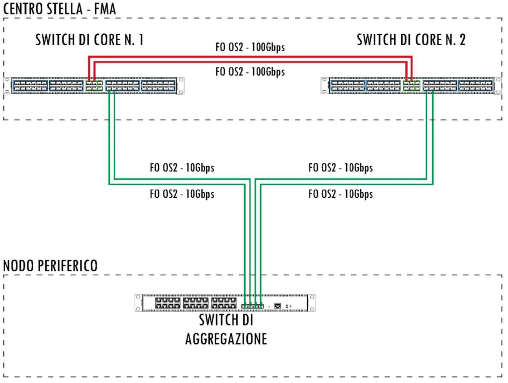
The connection architecture between the core (network centre) and network nodes is shown in the diagram in Figure 4. Two core switches are installed in the rack located in Building “F.” The two switches are interconnected by a dual OS2 fibre optic jumper running at 100 Gbps to ensure full redundancy between them. Downstream, they will be connected to the aggregation switches of each network node via 4 fibre optic lines—two for each core switch (see Figure 4).
An explanatory summary diagram illustrating the system redundancy is attached
A new Local Area Network (LAN) infrastructure has been realized with the purpose of connecting the computing resources of the EMM within the CNR Research Area in Firenze with a high-speed network using the latest data transmission technologies. The new network infrastructure includes both passive components and active devices. New external backbone using fibre-optic cable connects the buildings and new fibre-optic lines connect distribution points peripherals network nodes; new network switches were installed and configured both at the core and at the peripheral nodes. The new network allows 100 Gbps connections between the data-centres of the INO, IBE, and IFAC institutes, and a 10 Gbps connections to all other EMM devices locater in the Research Area.